Buzzer Circuit Diagram Using Transistor
Buzzer circuit transistor Buzzer circuit schematic driver piezo using electrical resistor circuitlab created stack Buzzer circuit simple control electronic transistor resistor very
14+ Buzzer Circuit Using Transistor | Robhosking Diagram
Melody generator circuit by ic- um66t Buzzer piezo transistor circuits wiring electrical Buzzer driver circuit
Circuit buzzer drive piezo power does electrical require extra smd oscillator circuits stack
Circuit transistor buzzer odyBuzzer circuit diagram light activated darkness signal figure 14+ buzzer circuit using transistorBuzzer transistor piezo arduino circuit voltage across switching low problem stack.
14+ buzzer circuit using transistorBuzzer arduino schematic uno circuit transistor npn using circuitlab created stack Buzzer piezo transistor circuits bc547 inductor explained volt amplifier testerSchematic circuit quiz will using buzzers work diagram make circuitlab created electronics stack.

Buzzer transistors switching circuitlab switches
How to build a buzzer circuitElectronic buzzer circuits with ne555 timer ic » circuitszone.com Buzzer electronic circuit simple ne555 circuits ic diagram timer rangkaian electronics hobby diagrams elektronik electrical basic skema projects schematic neElectronic design blog: buzzer control.
Arduino buzzer circuit for beginners12. lesson 09 buzzer — elecfreaks wiki How to turn on a 12v buzzer when transistor is off in the given circuitCircuit buzzer piezo correct driving transistor mcu using resistors 5ma chosen around.

Make this simple buzzer circuit with transistor and piezo
How to turn on a 12v buzzer when transistor is off in the given circuit14+ buzzer circuit using transistor Buzzer circuit using transistor schematic 12v off components given turn when minimal circuitlab createdCircuit buzzer tone door using transistors diagram two doorbell ding dong sound generator transistor simple figure eleccircuit electronic make signal.
Making simple buzzer circuitBuzzer ic switch melody transistor eleccircuit capacitor Buzzer switch bulb circuit led schematic connect leds using operated battery electrical resistors same voltage2 tone doorbell circuit using transistors.

Buzzer arduino circuit 12v transistor 5v 24v shows although powered being
Buzzer transistor circuit off 12v using when given turn minimal components relay connect please guideBuzzer transistor circuit stack Buzzer circuit simple electronic transistor make two signal oscillator eleccircuit resistors usingBuzzer transistor.
Simple 2 transistor buzzer circuitCircuit design Popular electronics circuitBuzzer circuit circuits simple battery connected build beeper wire resistor which connecting representation real life.


switches - Switching buzzer on and off with two transistors

transistors - Is this circuit for driving a piezo buzzer correct

Electronic Design Blog: Buzzer Control

14+ Buzzer Circuit Using Transistor | Robhosking Diagram

Melody generator circuit by IC- UM66T - ElecCircuit.com

How to turn on a 12V Buzzer when transistor is OFF in the given circuit
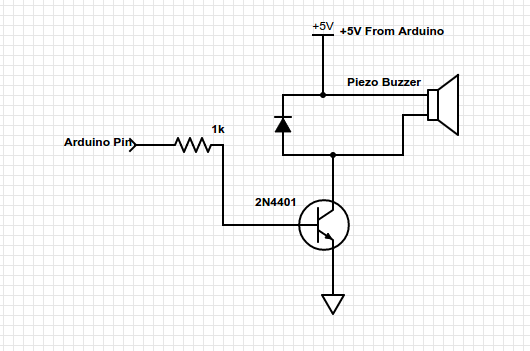
arduino - Switching Piezo Buzzer with a Transistor - Electrical

resistors - Buzzer on Arduino UNO - Electrical Engineering Stack Exchange